Sub-Slab/Sub-Membrane Depressurization System
Enkavent Installation Guide
These suggestions represent generally accepted procedures for successful installation of Low & Bonar Building Products.
These instructions may be followed, modified, or rejected by the owner, engineer, radon mitigation specialist, contractor
or their representative since they, not Low & Bonar Inc., are responsible for planning and executing procedures
appropriate to a specific application.
Subgrade Preparation for Enkavent Installation
Ensure subgrade is clean and free of large rocks, soil clods, or other debris that may interfere with
EnkaVent® system installation and performance.
Ensure subgrade is sloped such that low sections are not created where water could accumulate and
reduce or close off air/soil gas flow in the system
Enkavent Methods of Installation
There are 3 basic methods of EnkaVent® installation. The final design for any radon mitigation system is the
responsibility of the engineer and/or the radon mitigation specialist.
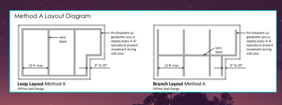
1. Method A places EnkaVent® inside the wall perimeter away from the footing.
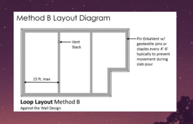
2. Method B aids in block wall depressurization by using the hinged edge section of EnkaVent® to fold
up against a concrete block foundation wall and capture radon gas that may infiltrate the structure at
the juncture of the foundation wall & the footing.
3. Method C places EnkaVent® in a crawlspace
4. All methods effectively capture radon gas so it can be evacuated through a passive or fan system.
Method A Installation- Basement and Slab-on-Grade Foundations
1. Unroll EnkaVent® with fabric backing towards the subgrade, aggregate layer, and footing
2. EnkaVent® can be installed to create a looped or branch layout. The looped layout insures that
sections of the vent mat never become isolated, preventing or reducing the evacuation of radon
gases. See Method A drawings.
3. Place the outer edge of EnkaVent® 8 to 20 inches from the perimeter wall depending on the design of
the system by the project engineer and/or the radon mitigation specialist.
4. Lay one or more lengths of EnkaVent® through the center of the subslab parallel to the longest wall or
cross ways perpendicular to the long walls. For larger slabs (>5000 square feet) multiple lengths should
be run such that the maximum spacing of the EnkaVent® is 15 foot on center.
5. Use geotextile staples, stakes or pins to keep the EnkaVent® in place so that continuous venting is
maintained and sections do not become isolated from the system.
6. Lay vapor barrier with minimum thickness of 6-mil (or 3-mil cross laminated) over the entire subgrade,
bringing it up and sealing at the perimeter walls. Thicker vapor barriers may be used with any EnkaVent
product. Vapor barrier should cover entire floor area and separate pieces should be overlapped 12
inches and sealed. All pipe and other penetrations should be sealed.

Method B Installation- Basement and Slab-on-Grade Foundations
1. Unroll EnkaVent® with fabric backing towards the subgrade, aggregate layer, and footing
2. EnkaVent® can be installed to create a looped layout. This insures that sections of the vent mat never
become isolated, preventing or reducing the evacuation of radon gases. See Method B drawing.
3. Fold 2 inch hinged portion so it is against the wall at the footing.
4. Attach EnkaVent® with power actuated fastener to footer at the hinge every 5 feet
5. At corners, cut away a 15 inch square of EnkaVent® , leaving the 2 inch hinge to overlay the abutting
EnkaVent® covered corner. Do not leave an overlap of EnkaVent® under the slab.
6. Lay one or more lengths of EnkaVent® through the center of the subslab parallel to the longest wall or
cross ways perpendicular to the long walls. For larger slabs (>5000 square feet) multiple lengths should
be run such that the maximum spacing of the EnkaVent® is 15 foot on center.
7. Use geotextile staples, stakes or pins to keep the EnkaVent® in place so that continuous venting is
maintained and sections do not become isolated from the system.
8. Adhere 2 inch expansion joint stripping along wall directly above the EnkaVent® matting.
9. Lay vapor barrier with minimum thickness of 6-mil (or 3-mil cross laminated) over the entire subgrade,
bringing it up the walls into contact with the expansion joint stripping where it is sealed. Thicker vapor
barriers may be used with any EnkaVent product. Vapor barrier should cover entire floor area and
separate pieces should be overlapped 12 inches and sealed. All pipe and other penetrations should
be sealed.

Method C Installation- Crawlspace Foundations
1. Unroll EnkaVent® with fabric backing towards the subgrade, aggregate layer, and footing
2. EnkaVent® can be installed to create a looped or branch layout similar to Method A layout drawings.
The looped layout insures that sections of the vent mat never become isolated, preventing or reducing
the evacuation of radon gases. See drawings.
3. Lay vapor barrier with minimum thickness of 6-mil (or 3-mil cross laminated) over the entire subgrade,
bringing it up and sealing at the perimeter walls. Thicker vapor barriers may be used with any EnkaVent
product. Vapor barrier should cover entire floor area and separate pieces should be overlapped 12
inches and sealed. All pipe and other penetrations should be sealed.
Vent Riser Pipe (applies to all methods & layouts)
1. All Radon systems require a vent riser pipe. For radon ready systems the vent may be capped on the
interior side of the floor slab. For a complete system pipe extends through the structure and roof and
may require an inline fan. Consult appropriate codes and regulations.
2. In the desired location for the vent risers(s), cut a hole in the vapor barrier to allow a 3 or 4 inch
diameter PVC flange fitting. Place fitting with the flange down, directly to the top of the EnkaVent. The
female part of the fitting goes through the hole in the vapor barrier. Cement a pipe stub to the fitting
which is long enough to extend through the concrete slab. Tape around the pipe fitting and the hole in
the vapor barrier. It is recommended to create a suction pit under the EnkaVent at the vent riser
location(s) using aggregate or several layers of EnkaVent.
3. Specifications are prepared by the appropriate design professional and will specify the number & size
of the vent risers.
Other Conditions & Considerations
1. Soil gas enters a structure through any openings in the floor slab such as concrete joints,
slab/foundation wall joints, duct, pipe or conduit penetrations through the slab, and other openings or
access points through the slab or to crawl spaces. These openings should all be properly sealed.
2. In larger buildings parts of the subgrade may be separated by grade beams, footings with walls, or by
changes in elevation.
To the best of our knowledge, the information contained herein is accurate. However, Low & Bonar Inc. and Global Plastic Sheeting Inc cannot assume
any liability whatsoever for the accuracy or completeness thereof. Final determination of the suitability of any
information or material for the use contemplated, of its manner of use and whether the suggested use infringes any
patents is the sole responsibility of the user. These products may be covered by patents or patents pending.
-

-

-

Do you have a quick Enkavent question?
Call us from a landline at 760 597 9298


